(Part:-1) Voyager 1: The Epic Journey Beyond Our Solar System and What It Reveals About the Universe

Voyager 1 is a space probe launched by NASA on September 5, 1977, as part of the Voyager program to study the outer Solar System and the interstellar space beyond the Sun’s heliosphere. Launched 16 days after its twin, Voyager 2, it communicates through the NASA Deep Space Network (DSN) to receive routine commands and to transmit data to Earth. NASA and JPL provide real-time distance and velocity data.

As of December 2024, it is the most distant human-made object from Earth at a distance of 166.28 AU (24.9 billion km; 15.5 billion mi). The probe made flybys of Jupiter, Saturn, and Saturn’s largest moon, Titan. NASA had the option of either doing a Pluto or Titan flyby; exploration of the moon took priority because it was known to have a substantial atmosphere. Voyager 1 studied the weather, magnetic fields, and rings of the two gas giants and was the first probe to provide detailed images of their moons.

Voyager spacecraft model
Artist’s rendering of the Voyager spacecraft design

As part of the Voyager program and like its sister craft Voyager 2, the spacecraft’s extended mission is to locate and study the regions and boundaries of the outer heliosphere and to begin exploring the interstellar medium. Voyager 1 crossed the heliopause and entered interstellar space on August 25, 2012, making it the first spacecraft to do so. After two years, the Voyager 1 spacecraft started encountering a third series of coronal mass ejections from the Sun that continued to at least December 15, 2014, further confirming that the probe is in interstellar space.

In 2017, the Voyager team successfully fired the spacecraft’s TCM thrusters for the first time since 1980, allowing the mission to extend an additional two to three years. Voyager 1’s extended mission is anticipated to continue sending back scientific data until, at the minimum, 2025, and could last until 2030, at its longest. Its RTGs may be able to provide enough electric power to return engineering data until 2036.

Mission background

History

A 1960s plan for a Grand Tour to examine the outer planets prompted NASA to initiate a project in the early 1970s. Knowledge acquired by the Pioneer 10 spacecraft enabled the engineers to design Voyager more capable of tolerating the powerful radiation surrounding Jupiter. However, at the last minute, kitchen-grade aluminum foil strips were placed on some of the cables in order to improve the radiation protection.

Voyager 1 was originally designed as Mariner 11 of the Mariner program. Budget cuts reduced the mission to a flyby of Jupiter and Saturn and renamed the mission the Mariner Jupiter-Saturn probes. The name was changed to Voyager when the probe designs began to differ substantially from Mariner missions.

Spacecraft components

Voyager 1 was constructed by the Jet Propulsion Laboratory (JPL). It has 16 hydrazine thrusters, three-axis stabilization gyroscopes, and referencing instruments to maintain the probe’s radio antenna pointing toward Earth.

Collectively, these instruments are part of the Attitude and Articulation Control Subsystem (AACS), along with redundant units of most instruments and eight backup thrusters. The spacecraft also included 11 scientific instruments to study celestial objects such as planets as it travels through space.
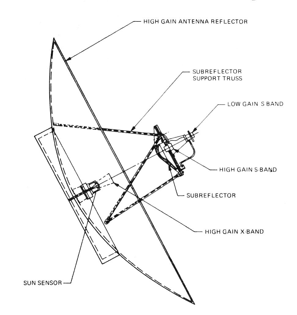
Voyager Program High gain antenna diagram
The 3.7 m (12 ft) diameter high gain dish antenna used on the Voyager craft

Communication system

Voyager 1’s radio communication system was developed to be utilised up to and beyond the limits of the Solar System. It carries a 3.7-metre (12 ft) diameter high-gain Cassegrain antenna for the transmission and reception of radio waves through the three Deep Space Network stations on the Earth. The spacecraft normally transmits data to Earth over Deep Space Network Channel 18, using a frequency of either 2.3 GHz or 8.4 GHz, while signals from Earth to Voyager are transmitted at 2.1 GHz.

Interstellar probes trajectory
Heliocentric positions of the five interstellar probes (squares) and other bodies (circles) until 2020, with launch and flyby dates. Markers denote positions on 1 January of each year, with every fifth year labelled.

Plot 1 is viewed from the north ecliptic pole, to scale.
Plots 2 to 4 are third-angle projections at 20% scale.
In the SVG file, hover over a trajectory or orbit to highlight it and its associated launches and flybys.

When Voyager 1 is unable to communicate with the Earth, its digital tape recorder (DTR) can record about 67 kilobytes of data for later transmission. As of 2023, signals from Voyager 1 take more than 22 hours to reach Earth.

Power

Voyager 1 carries three radioisotope thermoelectric generators mounted on a boom. The MHW-RTG consists of 24 pressed plutonium-238 oxide spheres. At launch, the RTGs produced approximately 470 W of electric power, with the remainder being waste heat. The power output of the RTGs degrades with time because the fuel has a half-life of 87.7 years, and the thermocouples deteriorate, but they will keep supporting some of its operations till at least 2025.
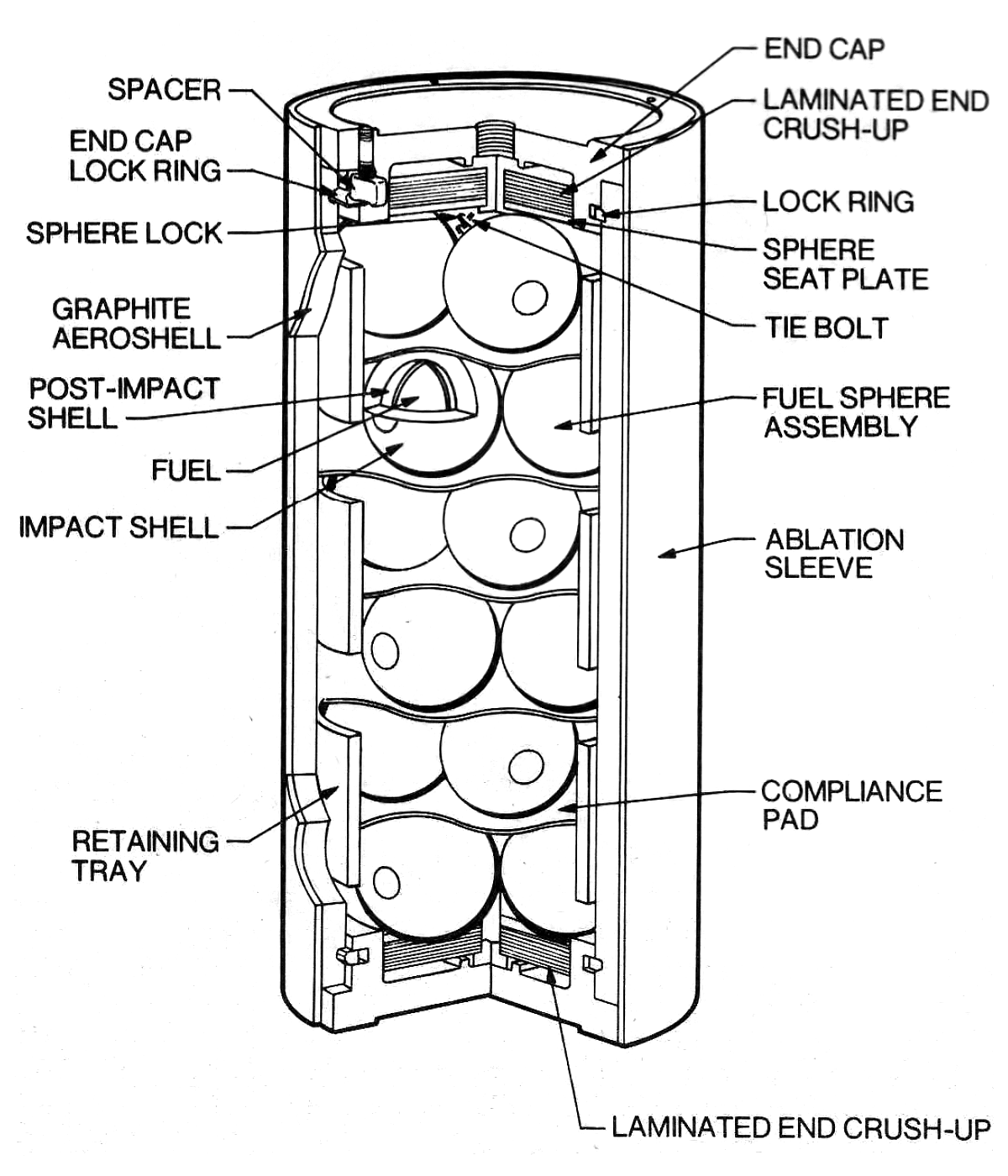
Voyager Program RTG diagram 1
Diagram of RTG fuel container, showing the plutonium-238 oxide spheres
Voyager Program RTG diagram 2
Diagram of RTG shell, showing the power-producing silicon-germanium thermocouples
Voyager Program RTG upclose
Model of an RTG unit

Computers

Unlike all other instruments on Voyager, the cameras for visible light are not autonomous; they are commanded from a parameter table in one of the spacecraft’s digital computers, the Flight Data Subsystem (FDS). Nearly all space probes have been launched since the 1990s with entirely autonomous cameras.

The cameras are controlled by the computer command subsystem (CCS). The CCS contains fixed computer programs such as command decoding, fault-detection and fault-correction routines, antenna pointing routines, and spacecraft sequencing routines. This computer is an upgraded version of the one used in the Viking orbiters of the 1970s.

The Attitude and Articulation Control Subsystem, or AACS, controls the spacecraft’s attitude. It ensures the high-gain antenna remains pointed at Earth, governs changes in attitude, and points the scan platform. AACS systems built for each Voyager are identical.

Scientific instruments
Instrument name Abbr. Description
Imaging Science System
(disabled)
(ISS) Used a two-camera system (narrow-angle/wide-angle) to provide images of Jupiter, Saturn and other objects along the trajectory.
Filters
Narrow-angle camera
Name Wavelength Spectrum Sensitivity
0 – Clear 280–640 nm
50px Voyager Filters Clear
4 – Clear 280–640 nm
50px Voyager Filters Clear
7 – UV 280–370 nm
50px Voyager Filters UV
1 – Violet 350–450 nm
50px Voyager Filters Violet
2 – Blue 430–530 nm
50px Voyager Filters Blue
5 – Green 530–640 nm
50px Voyager Filters Green
6 – Green 530–640 nm
50px Voyager Filters Green
3 – Orange 590–640 nm
50px Voyager Filters Orange
Wide-angle camera
Name Wavelength Spectrum Sensitivity
2 – Clear 280–640 nm
50px Voyager Filters Clear
3 – Violet 350–450 nm
50px Voyager Filters Violet
1 – Blue 430–530 nm
50px Voyager Filters Blue
6 – CH4-U 536–546 nm
50px Voyager Filters CH4U
5 – Green 530–640 nm
50px Voyager Filters Green
4 – Na-D 588–590 nm
50px Voyager Filters NaD
7 – Orange 590–640 nm
50px Voyager Filters Orange
0 – CH4-JST 614–624 nm
50px Voyager Filters CH4JST
  • Principal investigator: Bradford Smith / University of Arizona (PDS/PRN website)
  • Data: PDS/PDI data catalog, PDS/PRN data catalog
Radio Science System
(disabled)
(RSS) Used the telecommunications system of the Voyager spacecraft to determine the physical properties of planets and satellites (ionospheres, atmospheres, masses, gravity fields, densities) and the amount and size distribution of material in Saturn’s rings and the ring dimensions.
  • Principal investigator: G. Tyler / Stanford University PDS/PRN overview
  • Data: PDS/PPI data catalog, PDS/PRN data catalog (VG_2803), NSSDC data archive
Infrared interferometer spectrometer and radiometer
(disabled)
(IRIS) Investigates both global and local energy balance and atmospheric composition. Vertical temperature profiles are also obtained from the planets and satellites as well as the composition, thermal properties, and size of particles in Saturn’s rings.
  • Principal investigator: Rudolf Hanel / NASA Goddard Space Flight Center (PDS/PRN website)
  • Data: PDS/PRN data catalog, PDS/PRN expanded data catalog (VGIRIS_0001, VGIRIS_002), NSSDC Jupiter data archive
Ultraviolet Spectrometer
(disabled)
(UVS) Designed to measure atmospheric properties, and to measure radiation.
  • Principal investigator: A. Broadfoot / University of Southern California (PDS/PRN website)
  • Data: PDS/PRN data catalog
Triaxial Fluxgate Magnetometer
(active)
(MAG) Designed to investigate the magnetic fields of Jupiter and Saturn, the interaction of the solar wind with the magnetospheres of these planets, and the magnetic field of interplanetary space out to the boundary between the solar wind and the magnetic field of interstellar space.
  • Principal investigator: Norman F. Ness / NASA Goddard Space Flight Center (website)
  • Data: PDS/PPI data catalog, NSSDC data archive
Plasma Spectrometer
(defective)
(PLS) Investigates the microscopic properties of the plasma ions and measures electrons in the energy range from 5 eV to 1 keV.
  • Principal investigator: John Richardson / MIT (website)
  • Data: PDS/PPI data catalog, NSSDC data archive
Low Energy Charged Particle Instrument
(active)
(LECP) Measures the differential in energy fluxes and angular distributions of ions, electrons and the differential in energy ion composition.
  • Principal investigator: Stamatios Krimigis / JHU / APL / University of Maryland (JHU/APL website / UMD website / KU website)
  • Data: UMD data plotting, PDS/PPI data catalog, NSSDC data archive
Cosmic Ray System
(active)
(CRS) Determines the origin and acceleration process, life history, and dynamic contribution of interstellar cosmic rays, the nucleosynthesis of elements in cosmic-ray sources, the behavior of cosmic rays in the interplanetary medium, and the trapped planetary energetic-particle environment.
  • Principal investigator: Edward Stone / Caltech / NASA Goddard Space Flight Center (website)
  • Data: PDS/PPI data catalog, NSSDC data archive
Planetary Radio Astronomy Investigation
(disabled)
(PRA) Uses a sweep-frequency radio receiver to study the radio-emission signals from Jupiter and Saturn.
  • Principal investigator: James Warwick / University of Colorado
  • Data: PDS/PPI data catalog, NSSDC data archive
Photopolarimeter System
(defective)
(PPS) Used a telescope with a polarizer to gather information on surface texture and composition of Jupiter and Saturn and information on atmospheric scattering properties and density for both planets.
  • Principal investigator: Arthur Lane / JPL (PDS/PRN website)
  • Data: PDS/PRN data catalog
Plasma Wave Subsystem
(active)
(PWS) Provides continuous, sheath-independent measurements of the electron-density profiles at Jupiter and Saturn as well as basic information on local wave–particle interaction, useful in studying the magnetospheres.
  • Principal investigator: William Kurth / University of Iowa (website)
  • Data: PDS/PPI data catalog
Voyager1 Space simulator
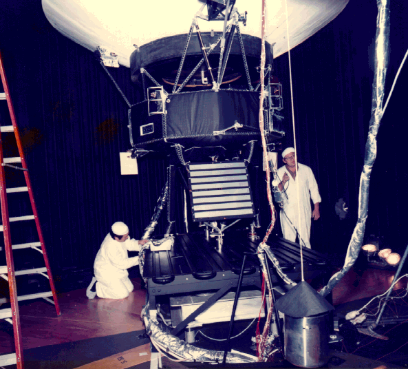
Voyager 1 ‘Proof Test Model’ in a space simulator chamber at JPL 3/12/1976
Record is attached to Voyager 1
Gold-Plated Record is attached to Voyager 1
Stone Voyager 4c
Edward C. Stone, former director of NASA JPL, standing in front of a Voyager spacecraft model
Voyager Instruments
Location of the scientific instruments indicated in a diagram

Mission profile

Timeline of travel

Voyager 1 skypath 1977 2030
Voyager 1‘s trajectory seen from Earth, diverging from the ecliptic in 1981 at Saturn and now heading towards the constellation Ophiuchus

Flyby of Jupiter

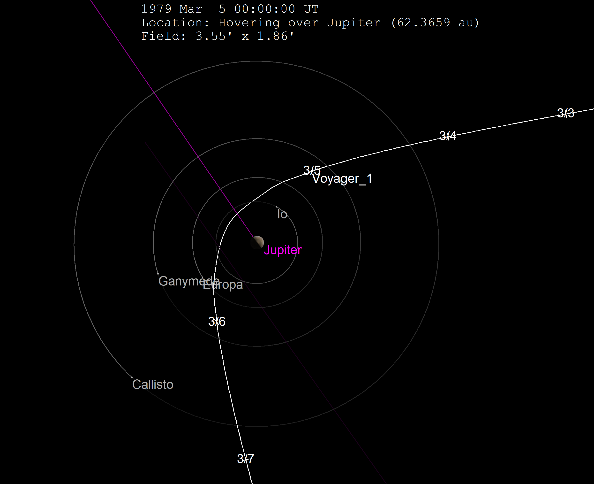
Voyager 1 started photographing Jupiter in January 1979. At the closest approach, Voyager 1 was on March 5, 1979. Voyager 1 passed Jupiter at approximately a distance of 349,000 kilometers (217,000 miles) from the Jupiter’s center. Due to the better photographic resolution achievable at closer proximity, most of the observations related to the moons, rings, magnetic fields, and the environment of the Jovian radiation belt were accomplished during the 48-hour time frame that encompassed the closest approach. Voyager 1 completed photography of the Jovian system in April 1979.

Animation of Voyager 1 trajectory around Jupiter
Animation of Voyager 1‘s trajectory from September 1977 to December 31, 1981
   Voyager 1  Â·   Earth Â·   Jupiter Â·   Saturn Â·   Sun

The discovery of ongoing volcanic activity on the moon Io was probably the greatest surprise. It was the first time active volcanoes had been seen on another body in the Solar System. It appears that activity on Io affects the entire Jovian system.

Io appears to be the primary source of matter that pervades the Jovian magnetosphere – the region of space that surrounds the planet influenced by the planet’s strong magnetic field. Sulfur, oxygen, and sodium, apparently erupted by Io’s volcanoes and sputtered off the surface by the impact of high-energy particles, were detected at the outer edge of the magnetosphere of Jupiter.
Voyager 1 Jupiter flyby March 5 1979
The trajectory of Voyager 1 through the Jupiter system

The two Voyager space probes made a number of important discoveries about Jupiter, its satellites, its radiation belts, and its never-before-seen planetary rings.

Voyager 1 time-lapse movie of Jupiter approach (full-size video)

Great Red Spot From Voyager 1
Jupiter’s Great Red Spot, an anti-cyclonic storm larger than Earth, as seen from Voyager 1
Volcanic crater with radiating lava flows on Io
View of sulfur-rich lava flows radiating from the volcano Ra Patera on Io
The eruption plume of the volcano Loki rises 160 km (100 mi) over the limb of Io
PIA01970
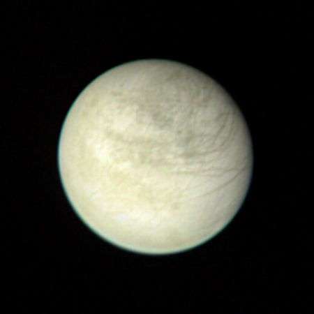
Europa’s lineated but un-cratered face, evidence of currently active geology, at a distance of 2.8 million km.
Ganymede PIA02278
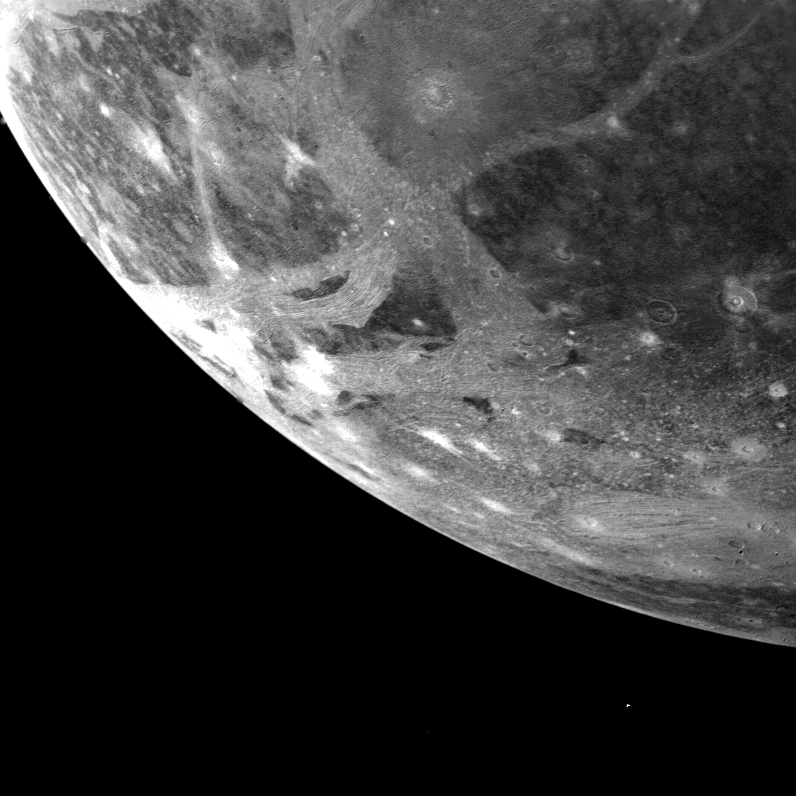
Ganymede’s tectonically disrupted surface, marked with bright impact sites, from 253,000 km.

Continue in the Next Part

Ayush Anand

Hi Friends, I am the Admin of this Website. My name is Ayush Anand. If you have any quarries about my any post so Leave the comment below.

Leave a Comment

Home
Search
Account

Discover more from ImagineInkjet

Subscribe now to keep reading and get access to the full archive.

Continue reading